
Tests & Results
Wire Gauge Comparison Test, Small & Large Loops

It is commonly said that wire gauge doesn’t affect loop performance, is this true? What if the loop is small, large, or has long lead-in lengths?
Purpose
- Test industry belief that wire gauge does not matter for loop performance.
- Observe and record if there is any difference in detection strength(performance) for large loops (6’x50’)made with solid or stranded wire.
- Observe and record if there is any difference in detection strength(performance) for large loops (6’x50’)made with 16AWG, 18AWG, 20AWG wire.
- Observe and record if there is any difference in detection strength(performance) for small loops (6’x6’) made with solid or stranded wire.
- Observe and record if there is any difference in detection strength(performance) for small loops (6’x6’) made with 16AWG, 18AWG, or 20AWG wire.
Hypothesis:
Solid wire will offer better performance than stranded wire due to its superior electrical characteristics (Lower resistance, better performance at high frequencies due to more surface area for skin effect).
Thicker wire (Lower wire gauge) will perform better than thinner wire (higher wire gauge) due to its superior electrical characteristics (Lower resistance, better performance at high frequencies due to more surface area for skin effect).
Materials:
- (1) 6’x50’ loop with 20’ of lead-in 24AWG Stranded (112’ perimeter loop) 2 turn loop
- (1) 6’x50’ loop with 20’ of lead-in 20AWG Stranded (112’ perimeter loop) 2 turn loop
- (1) 6’x50’ loop with 20’ of lead-in 18AWG Stranded (112’ perimeter loop) 2 turn loop
- (1) 6’x50’ loop with 20’ of lead-in 16AWG Stranded (112’ perimeter loop) 2 turn loop
- (1) 6’x50’ loop with 20’ of lead-in 16AWG Solid (112’ perimeter loop) 2 turn loop
- (1) 6’x6’ loop with 20’ of lead-in 16AWG Solid (24’ perimeter loop) 4 turn loop
- (1) 6’x6’ loop with 20’ of lead-in 16AWG Solid (24’ perimeter loop) 3 turn loop
- (1) 6’x6’ loop with 20’ of lead-in 16AWG Stranded (24’ perimeter loop) 3 turn loop
- (1) 6’x6’ loop with 20’ of lead-in 20AWG Stranded (24’ perimeter loop) 4 turn loop
- EDI LMA 1800 Detector
- EDI Oracle Detector
- Grooves cut into asphalt driveway to ensure all loops are placed in the same area and configuration.
- Sand bags to hold the loops in place
- Motorcycle – Honda CRF 250L
- Box Truck – Isuzu NPR
Procedure and Results:
6×50’ Loops (112’ perimeter, 300 Sq Ft)
The loops were laid out one at a time and placed into saw-cut grooves in the area where vehicles would be driving over the loops. The outer edges of the 112’ perimeter loop were held down with sand bags to prevent the wire from moving and causing false detections.
The Loop Finder and Oscilloscope were put onto stands and drilled into place over the loop wire in a designated area (on the long leg of the loop). An area was marked on the ground for laying down the metal rods so they would be placed over each loop in the same area.
The loops were connected to the detector modules and the following tests were run:
- Record the frequency that the detector tunes to.
- Lay the Aluminum rod over the loop in the designated area and record the detection.
- Lay the Steel rod over the loop in the designated area and record the detection.
- Record the reading on the Oscilloscope.
- Record the reading on the Loop Finder.
- Walk the motorcycle over the loop and continue adjust the sensitivity level to determine the lowest sensitivity level that will reliably detect the motorcycle.
- Using the lowest sensitivity level that can detect the motorcycle, begin to run the tests with the box truck.
- Record how far away from the loop the box truck is picked up.
- Record the detection strength when the front tire of the truck is centered over the front long leg of the loop.
- Record the detection strength when the front tire of the box truck is centered over the back long leg of the loop.
- Record the highest detection strength obtained as the box truck drives completely over the loop.
Detector Module Used: EDI Oracle S1EC
| 16 AWG Solid | 16 AWG Stranded | 18 AWG Stranded | 20 AWG Stranded | 24 AWG Stranded | |
| Frequency: | 27.6kHz | 27.7kHz | 27.3kHz | 26.9kHz | * |
| Oscilloscope Reading: | 4.5 | 2.8 | 2.4 | 1.2 | * |
| Loop Finder Reading: | 7 | 6 | 4 | 6 | * |
| Aluminum Rod: | Yes (9 Detection at 20 sensitivity) | Yes (7 Detection at 20 sensitivity) | Yes (7 Detection at 20 sensitivity) | Yes (7 Detection at 20 sensitivity) | * |
| Steel Rod: | No (No Detection at 20 sensitivity) | No (No Detection at 20 sensitivity) | No (No Detection at 20 sensitivity) | No (No Detection at 20 sensitivity) | * |
| For this section of the test, we use the lowest sensitivity setting of the detector module that was able to detect the motorcycle. This same sensitivity level was used to detect the truck: | |||||
| Motorcycle Detection: | YES | YES | YES | YES | NO |
| Sensitivity Level Setting: | 18 | 18 | 18 | 18 | 20 |
| Detection Strength: | 1,3 | 1,3 | 1,3 | 1,2 | NO |
| Front of truck detection distance: | 36” | 34” | 32” | 26.5” | * |
| Front Tire over front leg of loop detection strength: | 9 | 9 | 8 | 8 | * |
| Front tire over back leg of loop detection strength: | 12 | 12 | 12 | 11 | * |
| Highest detection as truck drives over loop: | 13 | 13 | 13 | 12 | * |
Click here to view in-depth test results on 24AWG loops: Large Loop – 16AWG vs 24AWG Detection Comparison.
Results of note:
The steel bar was never detected on the any of the loops, even at the highest sensitivity setting (20). The steel and aluminum bar are both the same size, but only the aluminum bar was detected. This is because aluminum is a much better conductor than steel.
The 16 AWG Solid loop always obtained better detection strengths than the 20AWG stranded loop. The 16 AWG Solid Loops had: 28.5% Increase in detection strength when comparing the aluminum bar.
35.8% Increased detection range when comparing the furthest distance the truck was detected.
12.5% Increase in detection strength when comparing the truck front tire test.
9.09% Increase in detection strength when comparing the truck front tire back loop leg test
8.33% Increase in detection strength when comparing the highest detection the truck obtained.
Detector Module Used: EDI LMA 1800
| 16 AWG Solid | 16 AWG Stranded | 18 AWG Stranded | 20 AWG Stranded | |
| Frequency: | 40kHz | 40kHz | 40kHz | 40kHz |
| Oscilloscope Reading: | 4.5 | 2.6 | 2.5 | 1.6 |
| Loop Finder Reading: | 7 | 6 | 5 | 7 |
| Aluminum Rod: | Yes (3 Detection at 9 sensitivity) | Yes (2 Detection at 9 sensitivity) | Yes (2 Detection at 9 sensitivity) | Yes (2 Detection at 9 sensitivity) |
| Steel Rod: | No (No Detection at 9 sensitivity) | No (No Detection at 9 sensitivity) | No (No Detection at 9 sensitivity) | No (No Detection at 9 sensitivity) |
| For this section of the test, we use the lowest sensitivity setting of the detector module that was able to detect the motorcycle. This same sensitivity level was used to detect the truck: | ||||
| Motorcycle Detection: | YES | YES | YES | YES |
| Sensitivity Level Setting: | 9 | 9 | 9 | 9 |
| Detection Strength: | 1,2 | 1,2 | 1,2 | 1,1 |
| Front of truck detection distance: | 24” | 20” | 17.75” | 16” |
| Front Tire over front leg of loop detection strength: | 4 | 4 | 3 | 3 |
| Front tire over back leg of loop detection strength: | 6 | 6 | 5 | 5 |
| Highest detection as truck drives over loop: | 7 | 7 | 6 | 6 |
Results of note:
The steel bar was never detected on the any of the loops with this detector module either. Even at the highest sensitivity setting (9). The steel and aluminum bar are both the same size, but only the aluminum bar was detected. This is because aluminum is a much better conductor than steel.
The 16 AWG Solid loop always obtained better detection strengths than the 20AWG stranded loop. The 16 AWG Solid Loops had:
28.5% Increase in detection strength when comparing the aluminum bar.
50.3% Increased detection range when comparing the furthest distance the truck was detected.
12.5% Increase in detection strength when comparing the truck front tire test.
9.09% Increase in detection strength when comparing the truck front tire back loop leg test
8.33% Increase in detection strength when comparing the highest detection the truck obtained.
6×6’ Loops (24’ perimeter, 36SqFt)
The loops were laid out one at a time and placed into saw-cut grooves in the area where vehicles would be driving over the loops.
The Loop Finder and Oscilloscope were put onto stands and drilled into place over the loop wire in a designated area (near the yoke). An area was marked on the ground for laying down the metal rods so they would be placed over each loop in the same area.
The loops were connected to the detector modules and the following tests were run:
- Record the frequency that the detector tunes to.
- Lay the Aluminum rod over the loop in the designated area and record the detection.
- Lay the Steel rod over the loop in the designated area and record the detection.
- Record the reading on the Oscilloscope.
- Record the reading on the Loop Finder.
- Drive the motorcycle over the loop and continue adjust the sensitivity level to determine the lowest sensitivity level that will reliably detect the motorcycle.
- Mark the center point on one leg of the loop with paint. Walk the motorcycle up to this point and stop when the motorcycles front tire is centered over the mark. Record the detection.
- Mark the center point of the loop with paint. Walk the motorcycle forward so that the front tire is touching this mark, this puts the motorcycle half way over the loop. Record the detection.
Detector Used: EDI ORACLE S1EC
All loops are in a 6×6’ pattern with 20’ of lead-in wire.
| 16 AWG SOLID 3 CONDUCTOR | 16 AWG SOLID 4 CONDUCTOR | 16 AWG STRANDED 3 CONDUCTOR | 20 AWG STRANDED 4 CONDUCTOR | |
| Oscilloscope Reading: | 6 | 8 | 6.75 | 9 |
| Loop Finder Reading: | 7 | 7 | 4 | 6.5 |
| Microhenry (µH) Reading: | 86 | 150 | 86 | 152 |
| Frequency: | 52.4kHz | 41.3kHz | 52.3kHz | 40.7kHz |
| Aluminum Rod: | DET STR: 2 SENS LVL: 9 | DET STR: 3 SENS LVL: 9 | DET STR: 1 SENS LVL: 10 | DET STR: 1 SENS LVL: 10 |
| Steel Rod: | NO | NO | NO | NO |
| Motorcycle – Front Tire on Loop | DET STR: 1 SENS LVL: 16 | DET STR: 2 SENS LVL: 16 | DET STR: 1 SENS LVL: 16 | DET STR: 1 SENS LVL: 16 |
| Motorcycle- ½ Way Over Center of Loop: | DET STR: 1 SENS LVL: 11 | DET STR: 1 SENS LVL: 11 | DET STR: 1 SENS LVL: 11 | DET STR: 0, 1 SENS LVL: 11, 12 |
Results of note:
The steel bar was never detected on the any of the smaller loops either. Even at the highest sensitivity setting (20). The steel and aluminum bar are both the same size, but only the aluminum bar was detected. This is because aluminum is a much better conductor than steel.
The improvements in performance are not as pronounced on the smaller loops as it is on the larger loops.
There is a trend that the 16 AWG 3 conductor and 4 conductor solid wires performed better than the 16 AWG 3 conductor stranded and 20 AWG 4 conductor stranded wires.
The 4 conductor 20AWG stranded wire loop had weaker detection strength in every test.
EDI LMA 1800
All loops are in a 6×6’ pattern with 20’ of lead-in wire.
| 16 AWG SOLID 3 CONDUCTOR | 16 AWG SOLID 4 CONDUCTOR | 16 AWG STRANDED 3 CONDUCTOR | 20 AWG STRANDED 4 CONDUCTOR | |
| Oscilloscope Reading: | 6 | 6 | 6.6 | 8 |
| Loop Finder Reading: | 7 | 7 | 6 | 8 |
| µHenry Reading: | 86 | 150 | 86 | 152 |
| Frequency: | 54kHz | 43kHz | 54kHz | 42kHz |
| Aluminum Rod: | DET STR: 2 SENS LVL: 5 | DET STR: 1, 2 SENS LVL: 4, 5 | DET STR: 1 SENS LVL: 5 | DET STR: 1 SENS LVL: 5 |
| Steel Rod: | NO | NO | NO | NO |
| Motorcycle – Front Tire on Loop | DET STR: 1 SENS LVL: 8 | DET STR: 1 SENS LVL: 8 | DET STR: 1 SENS LVL: 8 | NO DETECTION |
| Motorcycle- ½ Way Over Center of Loop: | DET STR: 1 SENS LVL: 6 | DET STR: 1 SENS LVL: 6 | DET STR: 1 SENS LVL: 6 | DET STR: 1 SENS LVL: 6 |
Results of note:
The steel bar was never detected on the any of the smaller loops either. Even at the highest sensitivity setting (9). The steel and aluminum bar are both the same size, but only the aluminum bar was detected. This is because aluminum is a much better conductor than steel.
The improvements in performance are not as pronounced on the smaller loops as it is on the larger loops. There is a trend that the 16AWG 3 conductor and 4 conductor solid wires performed better than the 16AWG 3 conductor stranded and 20AWG 4 conductor stranded wires.
The 4 conductor 16AWG Solid loop always obtained equal or better detection strengths than the other loops.
The 4 conductor 20AWG Stranded wire had weaker detection strength on the aluminum rod and front wheel of the motorcycle test.
Conclusion:
Q: Does wire gauge affect loop performance?
A: Yes.
Let’s get down to basics, this is the reason why wire gauge affects loop performance:
Wire gauge affects the performance of inductance loops. This is because thinner wire has more resistance than thicker wire. More resistance means more signal loss which decreases loop performance.
To understand why wire gauge is so critical for inductance loops, we must understand how the current flows through the wire. Inductance loops are powered at high enough frequencies that skin effect comes into play.
Skin effect describes the interesting way that AC (alternating current) travels down conductors, at higher frequencies current only travels through the outer edge of a round conductor. The easiest way to imagine what skin effect looks like is to think of the current traveling only around the outer skin of a conductor – the conductor is used like a hollow tube, all the copper in the center of the conductor is ignored.
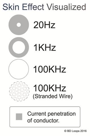
As you can see in the image above, at higher frequencies less of the conductor is used. At about 100kHz the signal only travels through the skin of the conductor. Loop detector frequencies range from 10kHz to 150kHz, skin effect diminishes the quality of the signal at these frequencies. In the case of stranded wire the skin effect will not take place on each strand – but just the outside of the stranded bundle. This is the reason wire gauge is so critical for inductance loops.
For gates/doors/parking/carwash applications the difference in performance can be easily seen when comparing large loops or loops with long lead-in lengths. (For a real-life example see BD Loops test: Large Loop – 16AWG vs 24AWG Detection Comparison).
Q: Does wire gauge affect loop performance?
A: Yes.
There was a noticeable trend in the test results, the loops made with thicker solid gauge wires performed the best. This is also because of skin effect.
In the case of stranded wire the skin effect will not take place on each strand – but just the outside of the stranded bundle. The gaps between the strands are essentially empty space that current cannot travel through, this creates more resistance for stranded wires.
Solid wire shines when used for the loop section of an inductance loop, as can be seen in this test. The solid wire loops obtained the strongest detections. You might be wondering why not make the entire loop and lead-in out of solid wire? That would increase the performance of the loop, but unfortunately the lead-in section must be made with stranded wire (for flexibility).
What this means, BD Loops Comments:
On Wire Gauge:
There is a pervasive myth in this industry that “Wire gauge doesn’t matter” for inductance loops. It is easy to understand why this myth is so popular, 20 & 18AWG wire is much less expensive than 16AWG wire.
BD Loops recommends that loops be made with 16AWG or thicker (lower wire gauge) wire. 16 AWG wire performs better than 18-20AWG wire for loops of all sizes. Best of all, with 16AWG wire you don’t have to worry about loop performance when wrapping large loops or installing loops with long lengths of lead-in.
When you wrap large loops or loops with long lengths of lead-in with thin wire, the resistance causes so much signal loss that detection strength will be greatly diminished and obtaining detections on small vehicles may be difficult. (For a real-life example see BD Loops test: Large Loop – 16AWG vs 24AWG Detection Comparison).
A major problem BD Loops sees with the myth that wire gauge doesn’t matter is that installers often buy spools of #18-#20 AWG wire unaware that the wire should not be used for large loops or for loops with long lead-in runs. Higher gauge (thinner) wire spools do not come with warnings explaining that they should only be used for small loops with short lead-in lengths. Installers are often under the false impression that they should not wrap loops larger than a 6×20 because thinner gauge wire is so common in our industry. Nobody ever explains to the installers that they can wrap larger loops, or have longer lead-in if they use lower gauge (thicker) wire.
At BD Loops we regularly make loops up to 6×50’ (112’ in perimeter) with 16AWG wire.
On Solid vs Stranded Wire:
Solid wire performs better than stranded wire. When developing the designs for our preformed loops BD Loops recognized that the superior electrical characteristics of solid gauge wire could allow loops to perform better. This is why we have been making our preformed loops with solid wire in the loop section and stranded wire in the lead-in section since day 1 over 16 years ago. The tests we have performed have proven that solid wire loops do perform better than stranded wire loops.
Final Thoughts:
Installing loops is time consuming, the best advice we can give installers is not to skimp on the loop design with thin wire (higher gauge). We suggest a minimum of 16 AWG be used for inductance loops.
You Might Find These Related Articles Interesting:
BD Loops
The Loop Experts!
BD Loops was founded in 2001. Their preformed loops and accessories are designed with the installer in mind. BD Loops offers a complete loop system solution including preformed direct burial loops, preformed saw-cut loops, loop sealant, blades, testing devices, and installation tools. BD Loops has a reputation for reliability and ease of installation. They pride themselves on the quality of their products and their commitment to providing excellent customer service and support. BD Loops preformed loops are made in the USA at their facility in Placentia, CA.