
Educational Articles
Training: Loops, Magnetism, and Twisted Lead-Ins

There is nothing confusing about an inductance loop, it’s just some copper in the ground. There are not any circuit boards, fuses, relays, or other complex pieces. But there is still a lot of confusion about how a loop works and how they should be designed. Each year advances are made in the industry, but only a handful of installers adopt them into their techniques. This often results in the same speculations/myths those instructors had, which were passed down from installer to installer thus creating the confusion we have today. By reading the rest of this training update you will have a clearer understanding of the myth surrounding twisted loop lead-in wire and “magnetic” loop detection.
The belief that loop lead-in wire heading back to the operator for gate installations must be twisted to prevent false detections or cross-talk is incorrect. The confusion comes from loops being used with traffic signals following the IMSA spec No. 50-2-84 lead-in wire, where it is required to twist and shield the lead-ins for transmission cables. The transmission cable is the wires from the pull box to control box that often runs over 200ft. The pull box is where all the loops’ lead-in join together to the transmission cables, there are usually 4 pull boxes per intersection that can have 5-15 loops run in one conduit leading to the control box. The reason why the IMSA spec was written was to solve the problem of cross-talk between those 5-15+ loops running through such long distances in the same conduit. The spec details the use of a special twisted, jacketed, and shielded wire for loop lead-ins to be connected then run from the pull box to the control box. The spec says nothing about loop lead-ins leading from the loop to the pull box.
There was a study commissioned by the U.S. Department of Federal Highway Administration and Texas Department of Transportation to test cross-talk. The results, “found no indication of false detections (due to cross-talk) over either twisted or untwisted lead-in wires at all sensitivity settings.”* In gate installations 2-4 loops are installed and where the lead-ins join together the distance to the operator is only a distance of 2 ft or less, too little of a distance for cross-talk to have any major effect. Gate installations do not use pull boxes so the above IMSA spec does not even apply to our industry. If lead-ins are ever run together over a distance of 2ft, it is recommended to keep the lead-in at least 2 inches apart from each other to eliminate cross talk.
It is recommended that if you wrap your own loops with 18AWG and larger and don’t use backer-rod that the lead-in wires be twisted 6 turns per foot, to prevent false detections from ground vibrations. Cross-talk can be reduced by using different frequencies in the detector. The reason why you twist your lead-in wires is so that the wires will not move. Wires that move even slightly can trip the detector causing phantom detections resulting in repeat service calls. Ground vibrations caused by cars, trains, horses, or even the gate itself can cause loose wires to move. This also applies to lead-ins leaving the saw-cut groove, they should be either twisted or jacketed to prevent any movement between the wires.
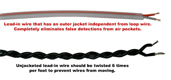
The advantages of not twisting your lead-in wires in a saw-cut application will result in decreased installation time, you will not have to cut a wider saw-cut groove or spend time manually twisting the wires, and use less wire since wire when twisted is shorter. Twisted wires have a higher chance of becoming nicked while being inserted into the saw-cut groove because the wires are stretched (have greater tension). Instead of twisting lead-in wires you can use jacketed lead-in wire. Using jacketed wire not only prevents movement but adds extra protection against nicks which could cause the wire to short. Understanding how a loop works will strengthen your knowledge about twisted lead-ins and add clarity to the other myth that loops detect through magnetism.
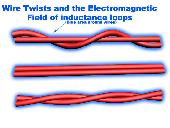
When a detector energizes a loop with an AC current the size of the loop, the number of windings in the loop, length of lead-in wire, and wire gauge will determine the total resistance or inductance of the loop circuit. The detector will record how much current is flowing through the loop and set that amount as the reference point. When a metal object enters the Electric Magnetic Field (EMF) field created by the loop’s AC current, the metal object absorbs some of the collapsing EMF fields. Now that some of the collapsing EMF field is absorbed, it lowers the resistance (inductance) of the loop circuit. This causes a decrease in inductance through the wire that is detected by the detector. When this happens, the detector will either open or close a relay switch that activates a preset command in the gate operator such as open, close, hold, or reverse.
Loops detect inductance as described above. It’s easy to see how the myth that loops detect magnetism became so common, especially since exit probes work off of magnetic north and loops create EMF (Electric Magnetic Field) fields. However the idea that loops detect only magnetic metals is easily disproved with aluminum. This causes a lot of confusion with installers who install aluminum gates under the assumption that the loops will not detect the gate since aluminum is not magnetic. Aluminum is a non-ferrous metal (does not contain iron), but aluminum can conduct electricity which can trip the detector through inductance. This obviously causes the gate to malfunction and the installer having trouble pinpointing the issue. If this mistake remains undiscovered upon completion of the installation, the customer will most certainly call and complain that their gate continually stays open resulting in a repeat service call.
*reference
Victor Bhagat and Donald L. Woods, P.E., NTIS document PB95216610 – Induction Loop Detector Systems Crosstalk, U.S. Department of Commerce, Aug 1994
This report is available on line from U.S. Department of commerce Research Report 1392-2.
BD Loops
The Loop Experts!
BD Loops was founded in 2001. Their preformed loops and accessories are designed with the installer in mind. BD Loops offers a complete loop system solution including preformed direct burial loops, preformed saw-cut loops, loop sealant, blades, testing devices, and installation tools. BD Loops has a reputation for reliability and ease of installation. They pride themselves on the quality of their products and their commitment to providing excellent customer service and support. BD Loops preformed loops are made in the USA at their facility in Placentia, CA.